
Categories
- Antarctic (192)
- Articles About RYM (13)
- Delivery stories (32)
- Life stories (71)
- Moutaineering – Aconcaqua, Island Peak (40)
- Personal Travel (106)
- Projects (26)
- Race Reports (150)
- Safety at Sea (19)
- South Georgia (314)
- Tips and tricks (51)
Archives
- September 2016
- February 2016
- September 2015
- February 2014
- December 2013
- November 2013
- October 2013
- June 2013
- May 2013
- April 2013
- February 2013
- January 2013
- December 2012
- November 2012
- October 2012
- September 2012
- August 2012
- July 2012
- June 2012
- May 2012
- April 2012
- March 2012
- February 2012
- January 2012
- December 2011
- November 2011
- October 2011
- September 2011
- August 2011
- July 2011
- June 2011
- May 2011
- April 2011
- March 2011
- February 2011
- January 2011
- December 2010
- November 2010
- October 2010
- September 2010
- August 2010
- July 2010
- June 2010
- May 2010
- April 2010
- March 2010
- February 2010
- January 2010
- December 2009
- November 2009
- October 2009
- September 2009
- August 2009
- July 2009
- June 2009
- May 2009
- April 2009
- March 2009
- February 2009
- January 2009
- December 2008
- November 2008
- October 2008
- September 2008
- August 2008
- July 2008
- June 2008
- May 2008
- April 2008
- March 2008
- February 2008
- January 2008
- December 2007
- November 2007
- October 2007
- September 2007
- August 2007
- July 2007
- June 2007
- May 2007
- February 2007
- January 2007
- September 2006
- August 2006
- July 2006
- June 2006
- May 2006
- March 2006
- June 2005
- May 2005
- February 2005
- January 2005
- December 2004
- June 2004
- September 2003
- August 2003
- June 2003
- October 2002
- March 2002
- February 2002
- September 2001
- August 2001
- April 2001
- August 2000
- July 2000
- November 1998
- July 1998
- June 1998
- August 1996
- 0
Tips and tricks
Lifelines and jackstays

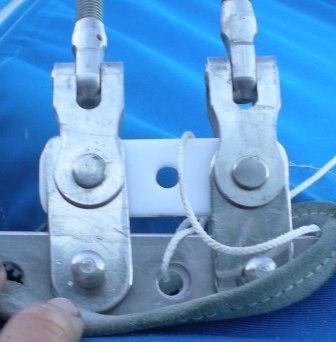
ORC Regs tell you about the length of the spectra lashing shown above in the picture and about how slack you can have the lifelines. However, one more thing that I like to do is to not trust the welds of the rings on the pushpit/pulpits and instead I take the spectra around the main tubing as well using the welded loop merely as a way of holding the lifelines at the right height.
| 3.14.2 | Lifelines required in Special Regulations shall be “taut”. | ||
|
| 3.14.6 | Lifeline Minimum Diameters, Required Materials, Specifications | ||
|
|||
| Notwithstanding 3.14.6 (a), temporary sleeving may be fitted provided it is regularly removed for inspection | |||
|
|||
|

I don’t know if you can tell but this jackstay is twisted – on purpose. The worst thing to hear when trying to sleep is the rattling of the jackstay on the deck. Putting the twists in stops this from happening and also makes it easier to pick up when trying to clip on. See below for some more good information – pay attention to a(i) in my mind the steering pedastals and the pulpit don’t comply with this rule. Better to be safe than sorry so I install padeyes spefically for the jackstay.
| 4.04 | Jackstays, Clipping Points and Static Safety Lines | |||
| 4.04.1 | The following shall be provided: | |||
|
||||
| shall be provided- | ||||
|
||||
|
||||
| US SAILING prescribes that jackstays may be of configurations other than 1 X 19. | ||||
|
||||
|
Sailtec backstay adjusters
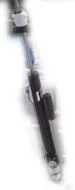
A few of my boats have these adjusters and mostly they work great. The owners of Sailtec are really nice helpful people. I was told that onve they stop holding pressure it is better just to chuck them out by one of my vendors and it probably is if you are paying for a rebuild however, if you do the work yourself it will save quite a bit of money. Below are some tips I got for the J105 pumps.
The full 9.5″ of throw should require no more than 55 or 60 strokes. If it takes more than that, there is air in the system.
If there is air in the system, it can be fixed by opening the valve all the way and, with the valve open, vigorously pumping the handle 20 – 30 times. This agitation will cause any bubbles in the oil to rise to the top, where they need to be.
They typically fill the cylinder so that it loses pressure within 3/8″ or so from max throw, in order that the system isn’t damaged from over pumping. If there is a significant variation, they can adjust it with more oil.
If the seals are leaking or you need to add oil:
Materials needed:
TUBE: TWO length of 3/8″ clear PVC tube/hose (clear so you can see what is coming out). About 3-feet each is about right.
OIL: Must be correct kind of oil- NOT automobile steering or brake fluid. Look for something called “Jack oil”. It is the stuff used in hand powered hydraulic pumps and car-jacks. It should be GOLD/Amber in color, NOT red, green, or black. Need “32” weight or less. Should have anti-foaming, and anti-corrosion.
2 ~quart-side plastic cups: 1 to pump old oil into, and 1 to “suck” new oil from.
1. Open the valve and extend the piston all the way (fully extended)
2. Turn upside down (piston pointing down)
3. Close release valve.
4. Put the unit in a bench vice (or equivalent) to hold it firmly upside down.
5. Pump a few times to “starve the pump”
6. Back off the nuts on the compression fittings, BOTH top and bottom, and remove the stainless steel return pipe/tube. It will be a tight fit, so you may need to “spring it” in to compress it slightly (be careful not to bend or buckle the tube!!).
7. Take one clear plastic tube to the stainless steel elbow by the pump (since the whole thing is upside-down, should be the top fitting). The tube may be tight, so puch or otherwise screw it on. Lead this to an empty cup/bucket. old oil will come out here.
8. Take the other tube and put it on the stainless steel elbow fitting that is now on the bottom, the one by the piston rod. Lead it to the bottom of a cup filled with fresh oil. Fill the tube with oil before you get it fully screwed on. Do everything you can to eliminate air bubble in the “fill” hose before the next step.
In my case, the oil came in a bottle with a conical shaped nipple, and it was easiest to just put the hose on the top of the bottle, and turn it upside down. Whatever your method, the goal is to fill with oil and no air bubbles.
*Important step*
9. AS SLOWLY AS YOU CAN…push the piston rod back into the unit. Don’t pump, just push the rod back into the body. Old oil will come out the top, “discharge” tube, and good oil will get sucked into the unit via the “fill” hose. Do this slowly so you don’t get air bubbles sucked in with the good oil.
If black oil comes out, this is very bad news. I guess it means that the internal seals are shot.
10. After the piston rod is fully inside the unit, put the stainless steel return pipe/tube back into position and tighten the compression nuts. There is no need to try to fill the pipe with oil prior to re-installing.
11. Take the unit out of the vice and turn it right-side up (normal position).
12. Open the release valve.
13. With your hands, manually extend the piston rod to full extension.
14. Close the release valve
15. Pump the unit all the way closed.
16. When the unit stops pumping, and the handle feels like it “snaps back”, hang the unit vertically upright (normal position) over a pan to catch excess oil.
17. Crack open the bottom return pipe/line compression nut and leak off a little oil. You may need to spring the return line slightly to open the seal at the bottom.
18. Then pump the piston back down and let the overflow leak off.
19. Close the bottom return pipe/line compression nut.
As an aside, if oil is leaking out of the pump at the bottom, they can sell you a $10 new pump seal. Easy to install, but do need a hammer at some point to drive out a roll-pin.
COLREGS
This last weekend the winner of the J105 fleet at Big Boat Series was unfortunately DSQ by the race committee on an alleged infringement of Rule 9 of the COLREGS. This made me realize how little the recreational sailors actually understand about the COLREGS. Most know not to get in the way of a frieghter but I think racers in particular need to learn them as well as we doing the RRS. I didn’t use to think this believe me – I justed stayed out of the way of big boats 🙂 It is important though as between sunset and sunrise the RRS are turned off in most SI’s and what you have to comply with is the COLREGS – so take the time to learn them as well as you learn the RRS.
BTW It is the law that any boat over 39 feet has to carry a copy onboard the vessel. You can download them from www.racingyachtmanagement.com/blog/documents/navrules.pdf
Tangs for short rigging
A customer unfortunately ended up with a bent rig after a collision and the tangs on the new rig were not in the same position. As there are Brogla turnbuckles (total $1000 for the set) which are permanently swaged on we had to shorten the rigging by the minimum amount possible by cutting off the top marine eyes and reswaging on new ones. Then we had to make up some tangs to lengthen the uppers by an inch. Instead of using ugly and heavy store bought parts some plates as in the attached picture were made up and installed.
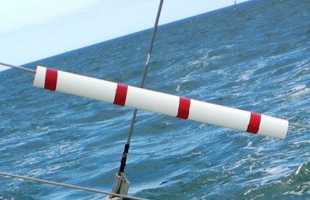
Protest flag
I have been doing some protest commitee work and one of the first things we must do is establish if the following rule was complied with.
61.1 Informing the Protestee
(a) A boat intending to protest shall inform the other boat at the first reasonable opportunity. When her protest concerns an incident in the racing area that she is involved in or sees, she shall hail ‘Protest’ and conspicuously display a red flag at the first reasonable opportunity for each. She shall display the flag until she is no longer racing.
I have found that the most effective way to store the protest and penalty flag on the boat is to attach them to the transom lifeline, roll them and cover them with turnbuckle covers. When the flag needs to be flown you simply move the cover to one side and the flag flies – no need for tape etc.
Etchells Rig
This week I worked on putting together a new etchells rig for a customer. It is a proctor (Seldon) rig from the UK which we had delivered on an etchells to the worlds in Chicago and then put on a boat from Fleet 12 who was at the worlds and they brought it back. Saved a bit in shipping. We measured the stiffness and I am using the following document to give me ideas on how to put the rig together. Maybe it will help you if you have an etchells. Forgot where I got it originally. Click here to download
Exploding Head II
So a while ago I wrote a blog entry called Exploding Head – about studying in Florida. Well tonight I received an email from a client of mine – Wayne who owns a Quest 33. I laughed so hard when reading it that I had to post it here…. Don’t read this if you are about to eat! I am very glad I wasn’t on the boat for this race!
“And here’s semi-amusing story re the head. For HMB, some unknown person apparently really had to go and used the head big time. Whomever had a problem pumping the bowl clean, as after the race, back at the dock, I discovered the smelly mess. After I found it, I too pumped and pumped, and made modest progress on moving the obstacle. There was so much pressure building up, it caused me to investigate. First, I removed the pump out cap on deck, thinking perhaps there was pressure lock. (Left the cap off, which figures in later.) Second, I traced the plumbing, as I pondered a possible dismantling of the head. Found the problem.
Someone had changed the Y valve to direct the head outflow to the overboard setting — we were way offshore, so no big deal. But, whomever had forgotten to also open the large sea cock, which meant that all he and later I were doing with our pumping was building pressure in the system between the head and sea cock. Voila. Now all I had to do to resolve things was to change the Y-valve back to the holding tank.
Feeling quite proud of my investigatory prowess, I implemented the plan and turned the Y-Valve. There was an immediate WHOOSH as the truly impressive amount of pressure the two of us had managed to get into that modest length of hose was released — which then drove a two foot geyser of #*% out of the pump out fitting on deck! I witnessed the geyser as my gaze followed the whoosh sound along the hose and out the port in the head. The people on the boat two slips down were beyond amused, and my sweater on deck will not be seen again. This story of course falls perfectly in that well worn boating expression “Shit happens.” (I have now put a nylon tie on the Y valve so if someone wants to change the discharge again, I will know and will remember to open the sea cock too. And despite the mess, I was happy that I did not have to rebuild the head.)”
Moral of the story – label the sea cocks and laminate an instruction sheet to post in the head!
On the Bermuda trip we had a head issue which turned out to be a result of baby wipes down the head. Rob heorically cleared the blockage when it was blowing mid 30’s and it involved removing cabinetry and the head door to fix the issue!
Moral of the story – don’t put things down the head if you haven’t eaten them.
3.14.6 Lifeline Minimum Diameters, Required Materials, Specifications
The reasoning behind a) is that the PVC cracks in the sun allowing water to sit inside the PVC against the wire and eventually it rusts and snaps when the crew are hiking out. This is not only unsafe but it will slow you down and you probably won’t finish the race!
a) All lifelines shall be stranded stainless steel wire of minimum diameter in table 8 below. Lifelines shall be uncoated and used without close-fitting sleeving. Notwithstanding 3.14.6 (a), temporary sleeving may be fitted provided it is regularly removed for inspection
b) Grade 316 stainless wire is recommended.
When using spectra to attach the lifelines I don’t just put the line through the ‘loop’ that is spot welding on the main pulpit/pushpit tube. I figure of 8 the line going through the loop around the pushpit through the loop and back to the eye in the lifeline. That way I am not relying on the spot welding on the pushpit/pulpit.
c) A taut lanyard of synthetic rope may be used to secure lifelines provided the gap it closes does not exceed 100 mm (4 in).
d) All wire, fittings, anchorage points, fixtures and lanyards shall comprise a lifeline enclosure system which has at all points at least the breaking strength of the required lifeline wire.
Table 8
LOA minimum wire diameter
under 8.5 m (28ft) 3 mm (1/8 in)
8.5m – 13 m 4 mm (5/32 in)
over 13 m (43 ft) 5 mm (3/16 in)
4.20.3 Liferaft Packing and Stowage
In Seahorse on the RORC club page the skipper of Holligan V described how difficult it was to access the liferaft when their yacht capsized.
‘Our liferaft was stowed at the stern of the cockpit sole with the knife for cutting the lashing attached to the tiller ahead of the raft – all now underwater and beyond reach. We all carry knives so one of us started to cut through the lashing to release the liferaft. With the stern submerged for muh of the time and at maximum reach for the rest of the time, this proved very difficult and exhausting. It took about half an hour to release the raft and by then the cold was getting to us. Frozen hands dropped the knife just as the last strands were cut through, and we were rapidly losin the ability to think rationally. We finally board the raft but found it impossible to bail with the flexible bailers provided.’
Some key lessons learnt from this experience.
* all crew should carry knives and small waterproof torches as a matter of course.
* liferaft stowage should be reviewed. Ours was accessible with the boat upside down. The four survivors would not be around if our raft had been safely stored in the locker.
Also attaching the liferaft with a hydrostatic release would be a lot safer.
A Liferaft shall be either:-
a) packed in a transportable rigid container or canister and stowed on the
working deck or in the cockpit, or:-
b) packed in a transportable rigid container or canister or in a valise and
stowed in a purpose-built rigid compartment containing liferaft(s) only and
opening into or adjacent to the cockpit or working deck, or through a
transom, provided that:-
i) each compartment is watertight or self-draining (self-draining
compartments will be counted as part of the cockpit volume except
when entirely above working deck level or when draining
independently overboard from a transom stowage – see OSR 3.09) and-
ii) the cover of each compartment is capable of being easily opened under
water pressure, andiii)
the compartment is designed and built to allow a liferaft to be removed
and launched quickly and easily, oriv)
in a yacht with age or series date before 6/01, a liferaft may be packed
in a valise not exceeding 40kg securely stowed below deck adjacent to
a companionway.
c) The end of each liferaft painter should be permanently made fast to a strong
point on board the yacht.
4.23 Pyrotechnic Signals
In Seahorse RORC Club page pyrotechnics were discussed….
The brightness of white flares varies significantly the best giving off 10K candela and the worst 2.5K. The only way to find out the candela is to check the manufactuere’s data sheet as it is not on the flare container.
During the Holligan V incident a wave dropped into the flare container which promptly sand along with the rest of the flares. A suggestion is to store them in a buoyant container. Also it was noted that flares have different ignition systems which are hard to read in the dark when in the water. The storage of flares needs to be accessible so that in the case of a capsize they are very easy to find.
|
red |
red |
white |
orange |
race |
|
6 |
4 |
4 |
2 |
MoMu0,1 |
|
4 |
4 |
4 |
2 |
MoMu2,3 |
|
|
4 |
4 |
2 |
Mo4 |
|
2 |
4 |
4 |
2 |
Mu4 |
TABLE 13
*Specifications
of white flares (except colour and candela rating)
should comply with the LSA Code Chapter III 3.2